15-494/694 Cognitive Robotics: Lab 4
I. Software Update and Initial Setup
At the beginning of every lab you should update your copy of
vex-aim-tools. To do this on Linux or Windows:
$ cd vex-aim-tools
$ git pull
II. Measuring the Camera Tilt
Translating camera coordinates to groundplane coordinates requires
knowing the camera pose. The camera is located 43.47 mm above the
groundplane. It is supposed to be tilted 18o down, but
there is considerable variation from one robot to the next. Thus, we
need to measure the camera tilt for each robot in order to calibrate
its vision system. Follow these steps.
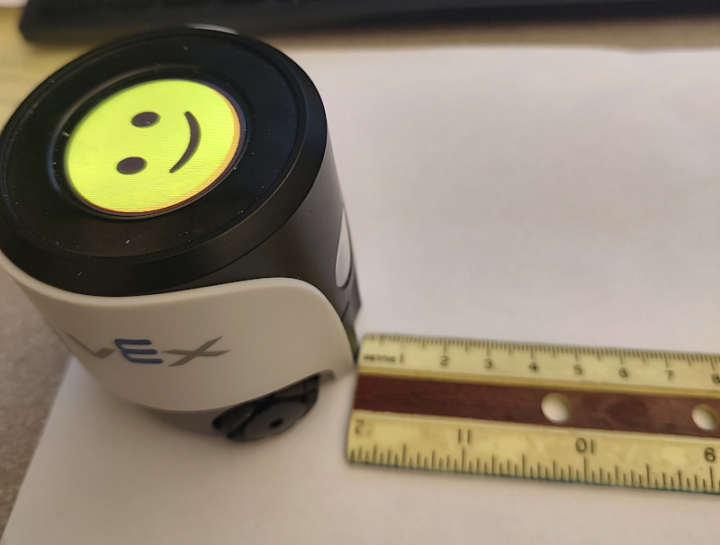
- Place a ruler in front of the robot so that the 0 mark of the
millimeter scale directly abuts the front of the robot, like this:
- Run simple_cli and type "show crosshairs" (or press "c" in the
camera viewer) to display a crosshairs in the camera viewer.
- Position the ruler so that the edge that is calibrated in
millimeters lies along the vertical crosshairs line, like
this:
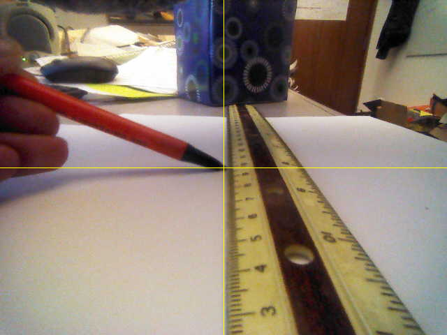
The other edge of the ruler will not be parallel with the
crosshairs line due to parallax effect. That's okay.
- Take the tip of a pen and position it at the center of the
crosshairs in the camera image.
- Read the distance value d at the pen tip on the ruler.
You should see a value between 90 and 120 mm. Note that the camera is recessed slightly and looks out
through a clear plastic window; add 3 mm to your d value to compensate for this.
- Calculate the camera tilt in degrees as atan2(43.47, d)
× 180/pi. You should get a value between 17 and 25 degrees.
- Q1: Report the calculated tilt value along with your robot number when you hand in your homework.
- In aim_fsm/aim_kin.py, edit the value of
camera_tilt to match your
measured value.
III. Effect of Calibrating Camera Tilt
- Obtain a VEX AIM Camera
Calibration sheet. Use a ruler to measure the distance from
the center of the robot template to the bottom edge of Aruco
marker 3 (should be around 64 mm) and Aruco marker 2 (should be
around 103 mm).
- Place the robot on the calibration sheet.
- Make a lab4 directory.
- Download Calibrate.fsm into your
lab4 directory, read the code, and compile with genfsm.
- Turn on the crosshairs in the camera viewer and turn the robot
so that the vertical line of the crosshairs runs through the exact
centers of the Aruco markers. Make sure the robot remains
positioned within the outline on the calibration sheet.
- Run the Calibrate program and note the pixel coordinates of the
four corners of Aruco marker 3. Camera images have a (width,
height) of (640, 480) pixels, and the origin (0,0) is the top left
corner.
- We want to find the pixel coordinates of the midpoint of the
bottom edge of marker 3. Modify the Calibrate program to compute
this from the corner information.
- Run the midpoint coordinates through robot.kine.project_to_ground() to calculate the coordinates of the point in the robot's base reference frame.
- Q2: Compare the result you calculated with the value you measured with the ruler.
- Make sure the robot's pose is at the origin by doing robot.set_pose(0,0,0,0) and then verify with "show pose".
- Place an orange barrel on top of Aruco marker 2 (not marker 3)
so that the bottom edge of the barrel lies on the bottom edge of the
marker.
- Q3: Do "show objects" and check the distance to the orange barrel.
How close does it come to the true distance?
- Edit aim_kin.py and replace your measured value of camera_tilt with the design spec value of 18 degrees.
- Q4: Run the orange barrel experiment again and compare the new
distance value with the old one.
- In vex-aim-tools/aim_fsm, do "git checkout aim_kin.py" to
restore the original version of the file.
IV. Examining Data Association
- Reset the robot's coordinate system by
doing
set_pose(0,0,0,0).
- Show the robot two orange barrels side-by-side, straight ahead
at a distance of around 150 mm. You can figure out which one is
OrangeBarrel.a and which is OrangeBarrel.b by doing "show objects"
and looking at the y-coordinate. Objects further to the left have
more positive y-coordinates because in the base reference frame, the
x axis points straight ahead and the y axis points to the left. You
can also hold your hand in front of one of the barrels and do "show
objects" to see which barrel is still visible.
- Remove OrangeBarrel.b and place it behind the robot. Since the
barrel's previous location falls within the camera field of view,
the robot knows that the barrel is not there, so the barrel is
treated as missing. The barrel disappears from the world map, and
"show objects" indicates that its state is now "missing".
- Do
Turn(180).now() to turn the robot around so it
sees the barrel you moved. Note that it is assigned the identity
OrangeBarrel.b again, i.e., we assume that this is the barrel that
went missing. Since OrangeBarrel.a is no longer visible, it is
dimmed in the world map, and "show objects" displays its state as
"unseen".
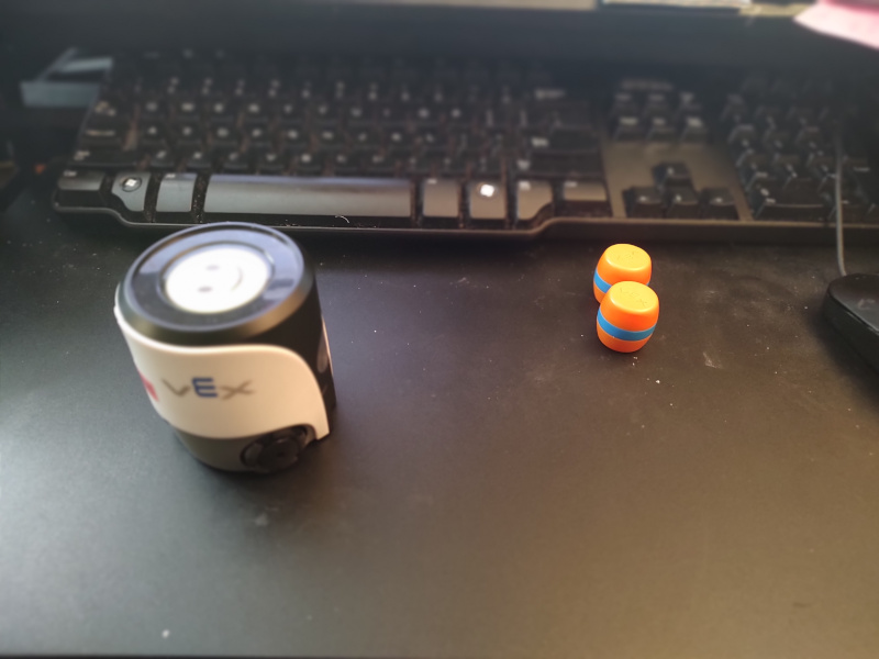
- Quit simple_cli. Position the two orange barrels so they are
side-by-side at a distance of 150 mm ahead of the robot, but far
to the left in its field of view:
- Start simple_cli and do "show objects". OrangeBarrel.a should
have a more positive y coordinate than OrangeBarrel.b, indicating
that OrangeBarrel.a is to the left of OrangeBarrel.b.
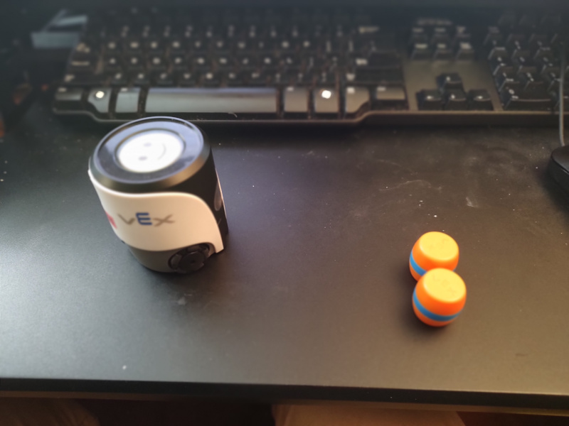
- Use one hand to block the camera, and slide both barrels to
near the right edge of the camera's field of view:
- Unblock the camera. Because both barrels are far from their
initial positions, neither matches a world map object, so the
greedy data association algorithm tries to make assignments, and
it may choose poorly. In other words, OrangeBarrel.a, which was
originally the barrel on the left (more positive y-coordinate),
might end up as the barrel on the right (less positive
y-coordinate). Q5: Document this with screenshots showing
the barrel configurations, the worldmap views, and the output of
"show objects".
V. Kinematics Calculations
- In simple_cli, type "show kine" to see the robot's kinematic
tree. Then type "show kine camera" to see the parameters for the
camera reference frame.
- Read through aim_fsm/aim_kin.py to see the detailed kinematic
structure of the robot.
- Read through aim_fsm/kine.py to understand how the forward
kinematics solver works.
- The camera reference frame has its origin at the center of the
camera image plane, with the x-axis pointing to the right, the
y-axis pointing down, and the z-axis pointing straight
out. Q6: Use joint_to_base('camera') from kine.py and the
translation_part() function from geometry.py to calculate the
position of the origin of the camera reference frame in base frame
coordinates.
- A fruit fly enters the AI Maker Space and hovers directly in
front of the robot's camera, at a distance of 20 mm from the
center of the camera image plane. Q7: Write down the fruit
fly's coordinates in the camera reference frame, using homogeneous
coordinates. Then write a Python expression using functions from
kine.py to calculate the location of the fruit fly in base frame
coordinates. Show the expression and your result.
VI. Homework Problems (Solve Individually)
- Display reference frame: read aim_fsm/aim_kin.py and
modify the file to add a reference frame for the color display on
the top of the robot. We want the origin to be at the center of
the display, with the z axis pointing up. Q8: Following the right
hand rule, if we want the top left corner of the display to have
negative coordinates and the bottom right corner to have positive
coordinates, how should the x and y axes be oriented?
- The Denavit-Hartenberg parameters (d, theta, r, alpha) that
take you from the joint i reference frame to the
joint i+1 reference frame allow you to position the
zi+1 axis however you like. But if you also
want to control the origin of the i+1 reference frame, the
four D-H parameters may not provide enough degrees of freedom. In
that case, we have to create a "dummy" joint between
joints i and i+1 so that we can perform the
coordinate transformation in two steps. An example of this can be
seen in the camera reference frame in aim_kin.py, where we had to
insert a "camera_dummy" joint in order to control both the
orientation and origin of the camera reference frame.
Q9: Modify aim_kin.py to define reference frames for the 3 wheels.
Each reference frame should have the z axis aligned with the
wheel's axle, pointing outward, with the y axis pointing up. The
origin should be at the center of the wheel. You will need a
dummy reference frame for each wheel to accomplish this.
Test your solution by choosing points next to the robot,
expressing them in the wheel's reference frame, using the
kinematics transformation matrix from joint_to_base() to convert
them to base frame coordinates, and making sure the results are
reasonable.
- Study the portion of the Celeste preamble that describes how to control the LEDs.
Try asking Celeste to do interesting things with her LEDs, such as:
- Please flash your LEDs in an alternating red and white pattern.
- Please count from 1 to 6, saying each number and then displaying an appropriate LED pattern for that number.
- Please set each LED to a color from the flag of Ireland.
- Please iterate through the nodes C, D, E, F, G, and play each note and display a different color as you play the note.
Q10: Make up three interesting LED prompts of your own, and refine them until they work properly.
What to Hand In
Hand in a zip file containing the following:
- Part II: your robot number and measured camera angle (Q1).
- Part III: Your answers to Q2, Q3, and Q4.
- Part IV: images and observations from your data association
experiment (Q5).
- Part V: the Python expressions and results from your two kinematics
calculations: camera origin (Q6) and fruit fly location (Q7).
- Part VI: Your modified version of aim_kin.py with the color display
reference frame and your answer to the question about orientation of
the axes (Q8), and your wheels reference frames (Q9).
- Part VI (continued): Your Celeste prompts for interesting LED
patterns (Q10).
|